
The Big Plans Print System based on CoreXY kinematics. Traditional cartesian-based printers used steppers oriented to the X and Y axes. Since the Y axes moves the X motor must also move with the axis. This means the X motor must be mounted to the Y gantry greating increasing the moving mass of the Y axis. In addition, the motor is offset to one side so there is also a weight imbalance so two steppers must be used on the Y axis to ensure the gantry moves evenly. Increasing mass means more inertia so generally more mass means slower acceleration and more artifacts (eg: 'echo') when changing direction. Increasing the rigidity of the gantry can counter-act some of these effects but the fast, precise movement of a 3D printer calls for a wholistic approach and you should try to reduce mass as well as improve rigidity where possible.
CoreXY requires only two steppers for X/Y motion and mounts the motors directly to the printer frame however doing so requires long GT2 cables and a pulley system which is a little harder to understand and debug that cartesian motion. For light-weight printheads (eg: bowden) CoreXY is clearly superior and can achieve incredible speeds but even for mid-weight heads (eg: single direct drive) CoreXY can outperform cartesian setups. Very heavy specialty heads may start to bump up against pulling limitations of the two motors or skipping of the GT cables under normal tension but that shouldn't be an issue on 'normal' hobby 3D printers.
In addition, the printer system uses linear rails on both the X and Y axes. Linear rails are superior to V-Slot wheels in that there is little wear over time, no need to tune or tension wheels, and they are not suceptible to inconsistencies in the extrusions that the wheels ride along. Linear rails are superior to linear rods in that rails are supported by 2020 extrusions and built from hardened steel making them less prone to bending or vibration. The carriage bearings are usually higher quality with less slop than the LM8UU bearings. The down-side is that linear rails cost 2-3x what you would spend on a wheel or rod-based system. In order to keep costs down I chose to use linear rails for X and Y movement but stuck with smooth rods for Z movement as there is little lateral movement or inertia to consider on the Z axis and a lot of folks likely already have smooth rods in their kit.
The X/Y gantry for the printer system requires:
In order to complete the gantry you will need to have an X-carriage printed and ready to mount. While we will build the extruder in a future step you have to decide which carriage you want to implement now. At the time of writing I have a direct drive carriage that utilizes a NEMA 17, an extruder that directly mounts a V6 radiator (eg: BMG or Titan), and a BLTouch. I also have a standard bowden carriage that works with a V6 cooler. Finally, I have a dual-extrusion bowden carriage that supports E3D Chimera/Cyclops style mounts. You must print one of those carriages and four GT2 cable clamps in order to proceed with the installation.
While 2020 are the most common extrusions used for the XY Gantry some may opt to use 2040 extrusions. The standard pully blocks assume a 2020 horizontal profile and would not fit a vertical 2040 extrusion. There are 2040-specific versions of the pully block bottoms that correctly align with the regular top blocks when installed in a vertical 2040 extrusion.
If you are using 2040 extrusions for the frame vertical components and then 2020 for the upper horizontal frame you then orient the top front extusion to be on the inside of the 2040 extrusion and the standard mounts should work normally. If the horizontal 2020 extusion is on the outside of the vertical 2040 extrusion then you will need to mount the blocks upside down and will not be able to pass-through the 2040 extrusion in a ladder-style design.
I have a video detailing the installation of this gantry however it's on a TronXY X5SA with vertical 2040 extrusions with the pulley blocks are mounted in the 'upside down' configuration. The concepts and general instructions are the same and it's still a useful reference. For this example we will assume a 2020 frame.
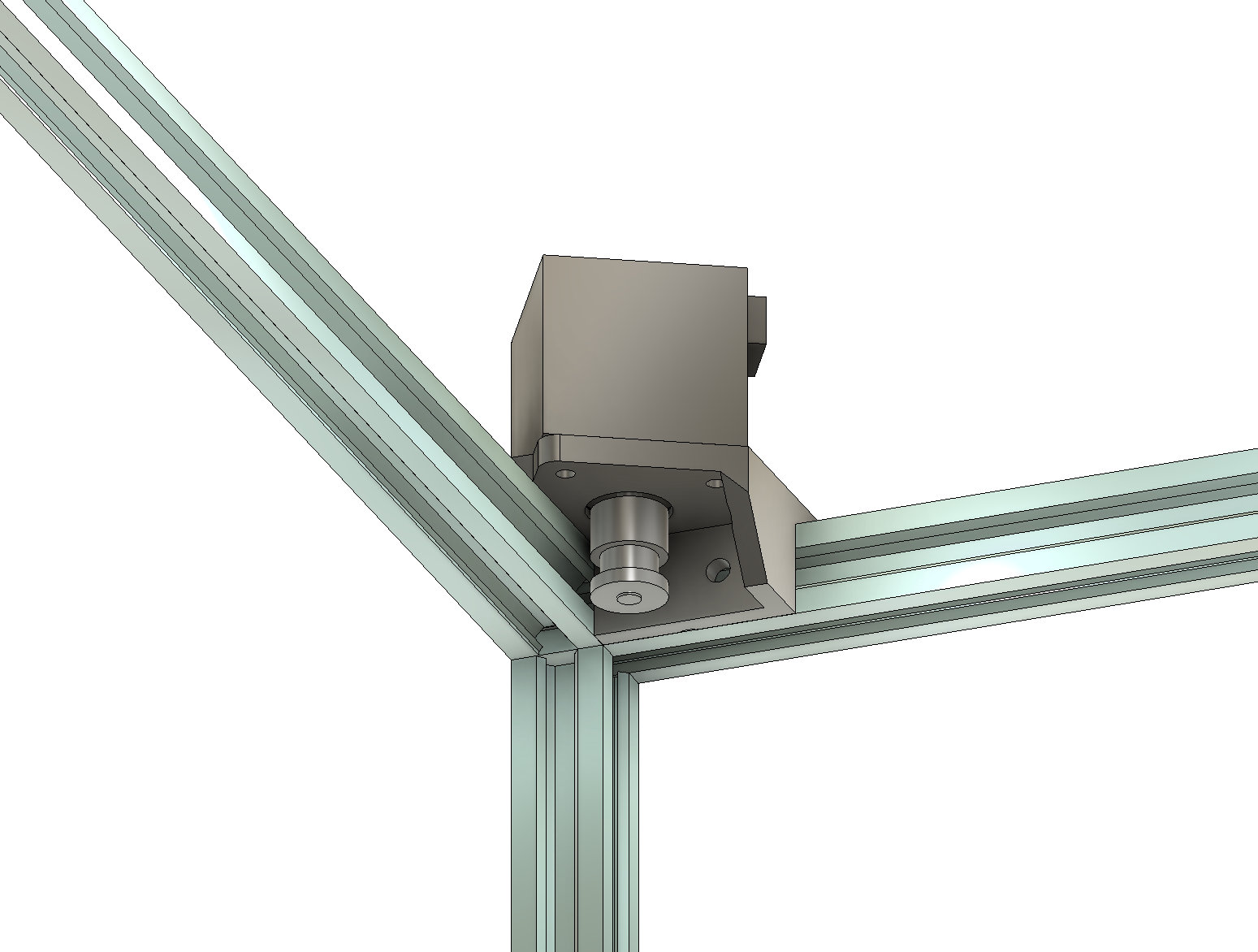
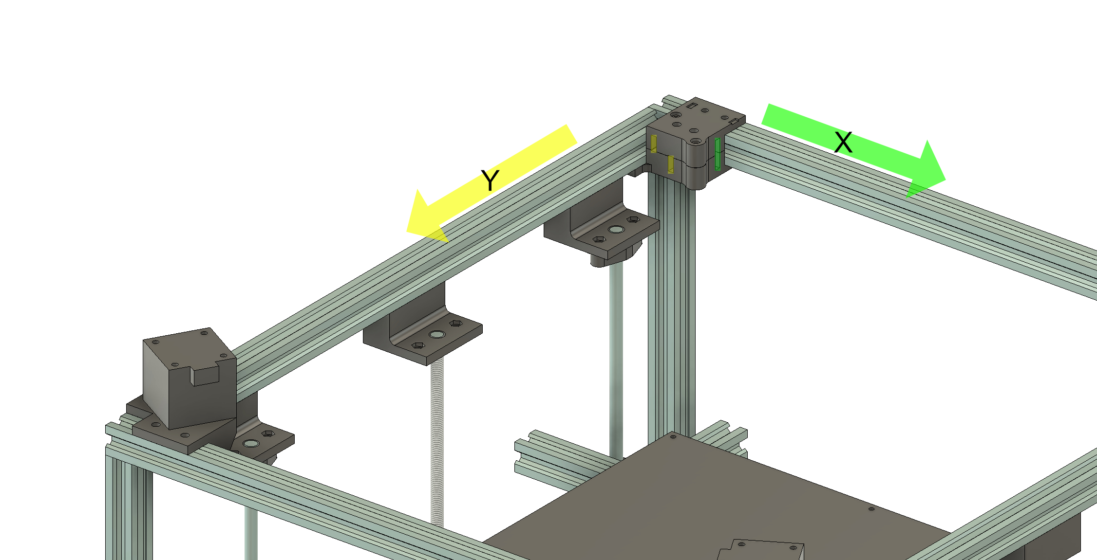
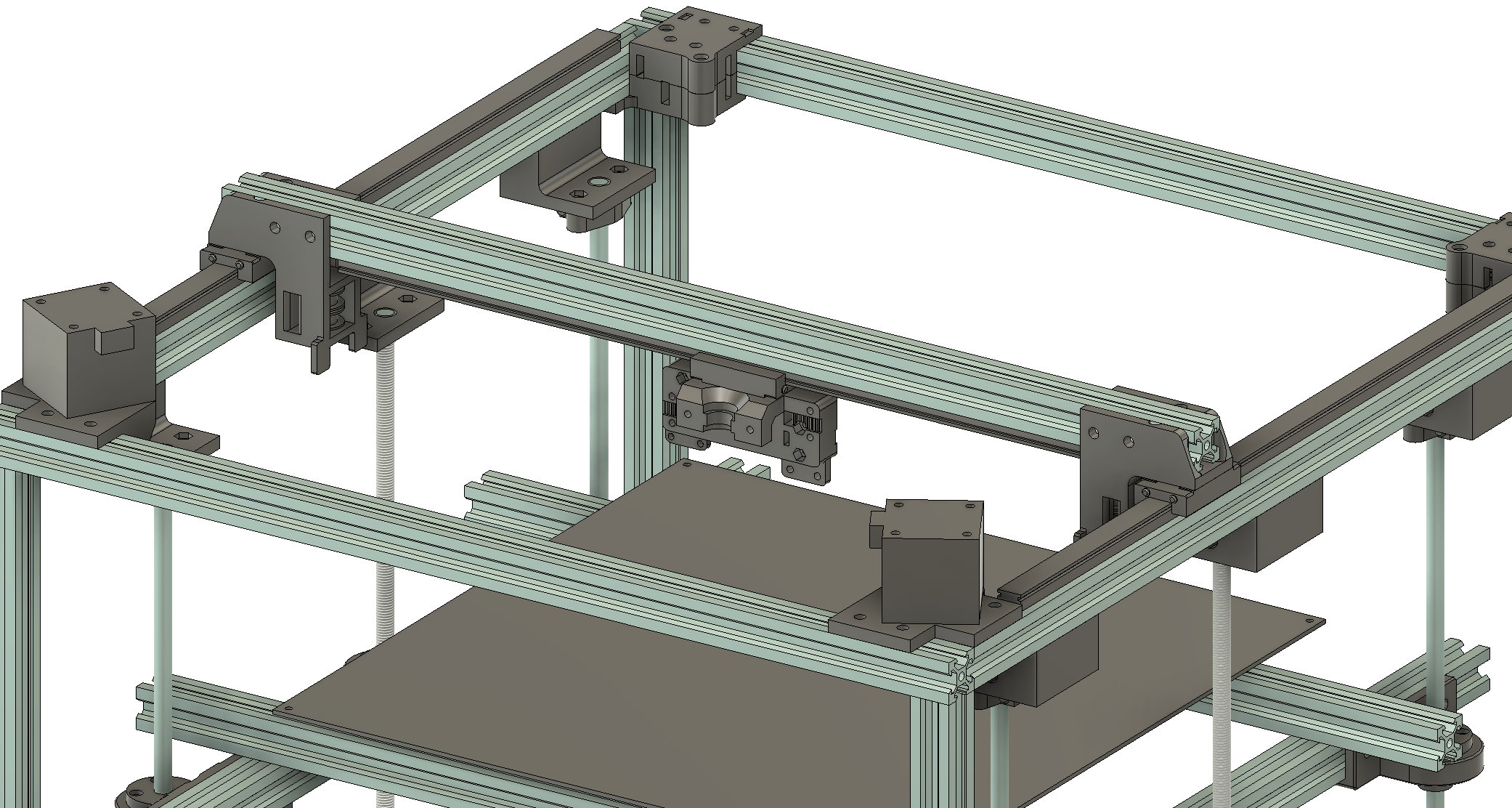
Starting with the motors, install a NEMA 17 stepper into each of the motor mounts such that the motor is opposite to the extrusion flanges. You can either mount the motors at the rear of the frame or at the front of the frame. I prefer the front mount as 1) The GT2 cables that run along the X axis will be located at the back of the printer and less likely to get in the way and 2) The motor mounts are slightly larger than the pully blocks which aligns well with the carriage as the front of the carriage is a little larger than the rear due to the hot end cooling fan. However, it's common to see the motors mounted in the rear corners and they take up more vertical space than pully blocks. The following images and instructions will reflect front-mounted motors.
The 'open' side of the mount should point along the Y axis. Each motor will require a timing pulley and they will mount in opposite positions but that will become obvious once the pulley blocks are installed.
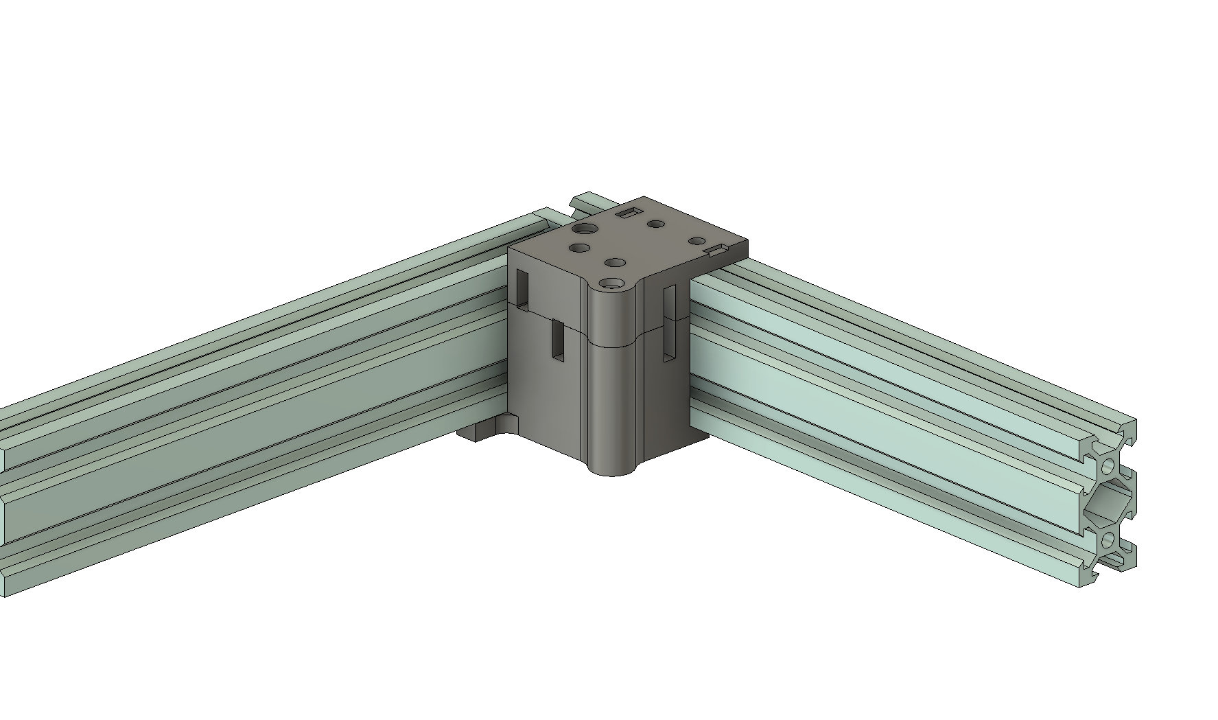
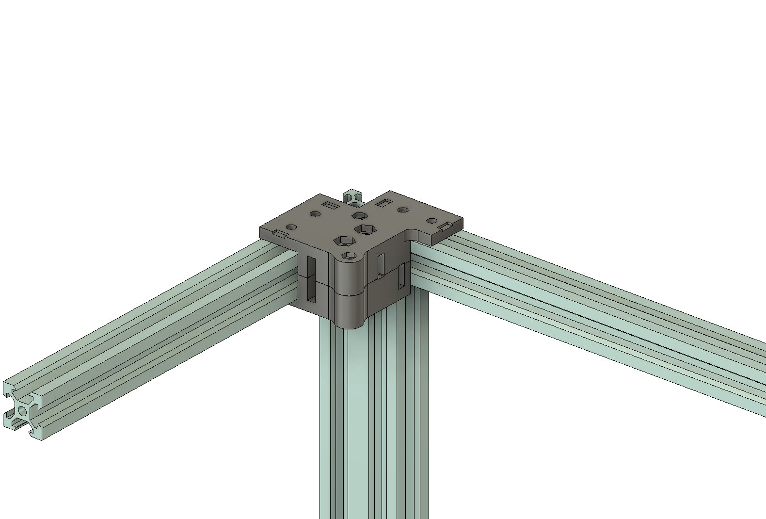
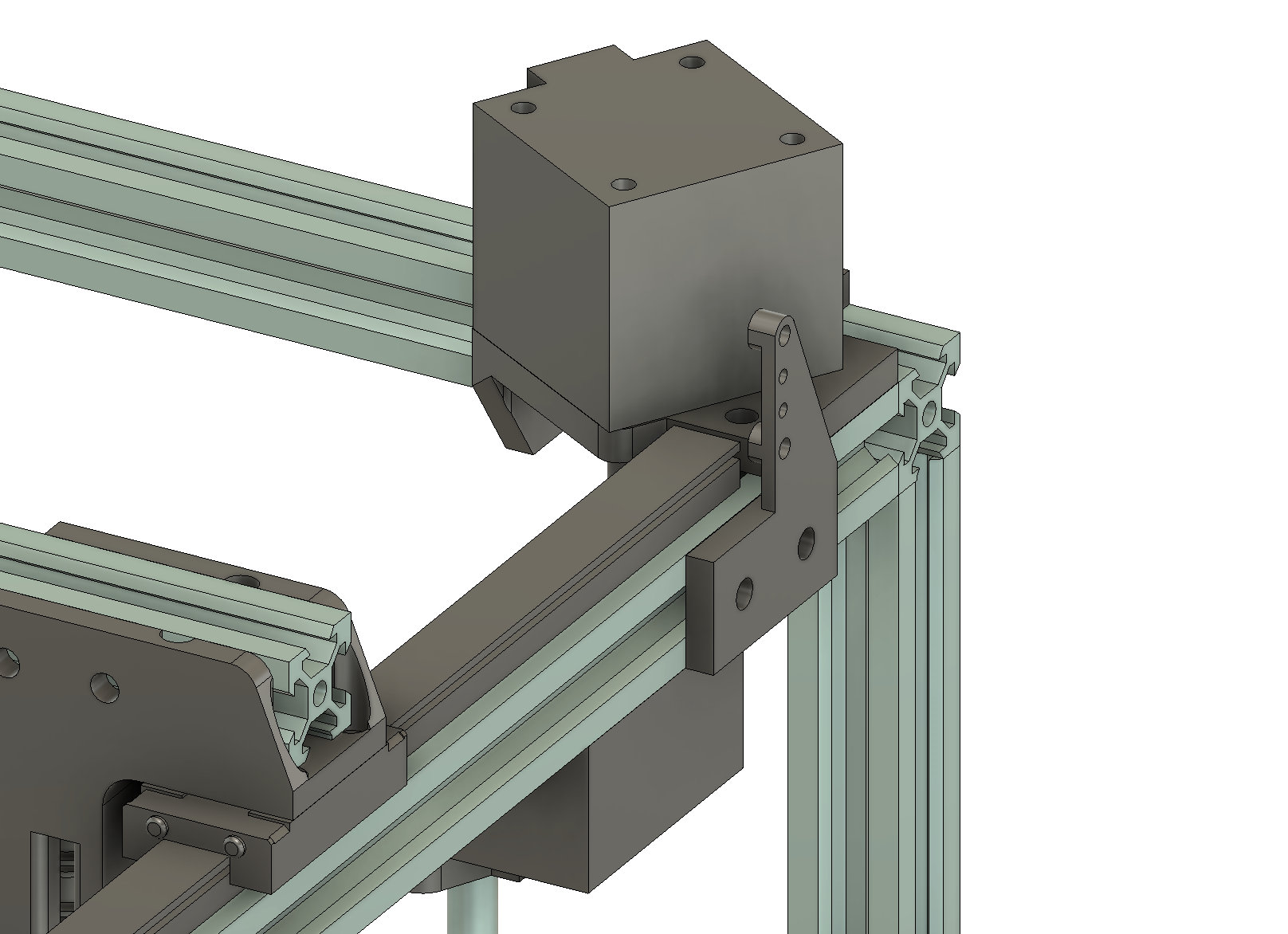
The pulley blocks each require two GT2 pulleys. The pulleys simply slot into the gaps in the pulley blocks - no spacers or anything required. The blocks are held together using m3 nuts and bolts and can be completely assembled before being attached to the frame. When inserting the m5 bolts, they can be inserted from the top and left without nuts however if you want to use m5 nuts be sure to be very gentle when tightening them. Any pressure at all could bend the mount and introduce friction. If the nut touches the plastic then it's tight enough.
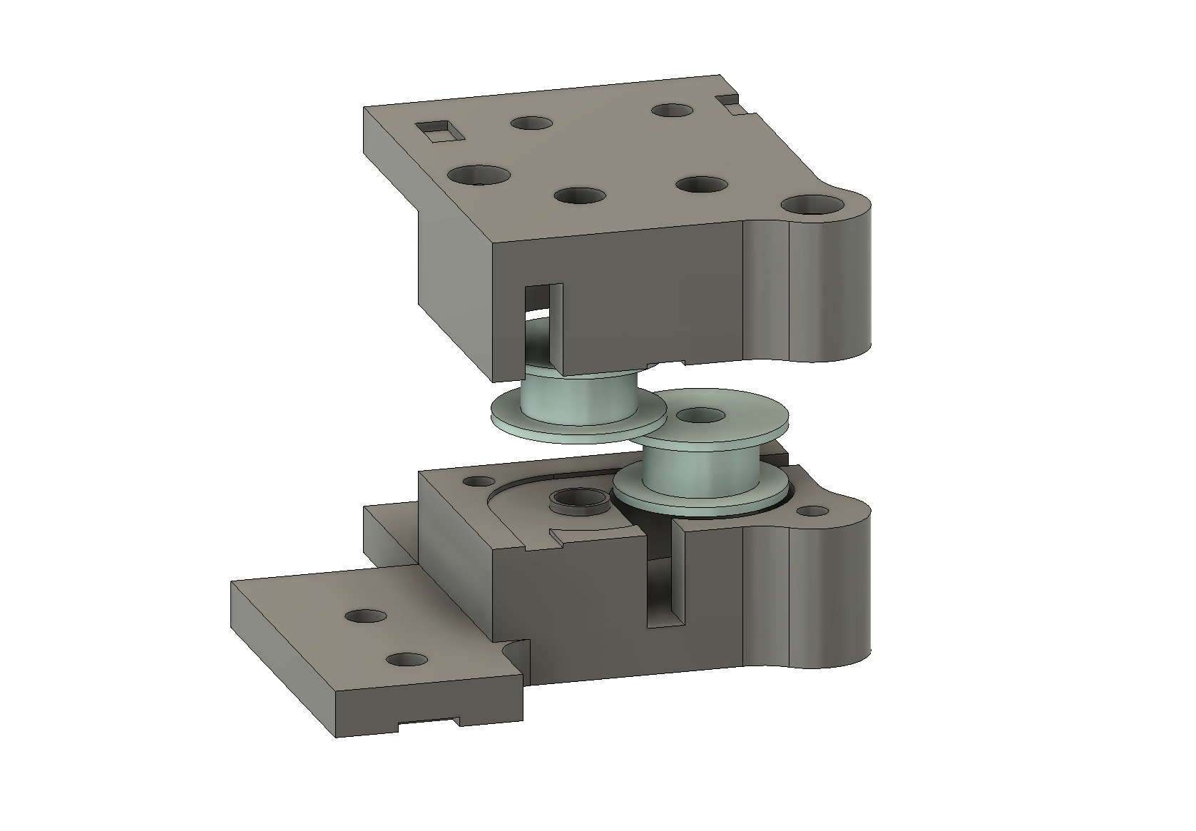
The blocks should be oriented such that the aligned cable exits go along the X axis while the offset cable exists go along the Y axis. There are notches in the blocks so that 2040 corners can still be used to secure the frame pieces.
The outer cable will determine the orientation of the timing pulley on the motor shaft. If the outer cable is on top, the timing pulley needs to be mounted with the teeth closer to the motor. If the outer cable is on the bottom the teeth should be mounted away from the motor. Final alignment can be performed once the carriage is assembled.
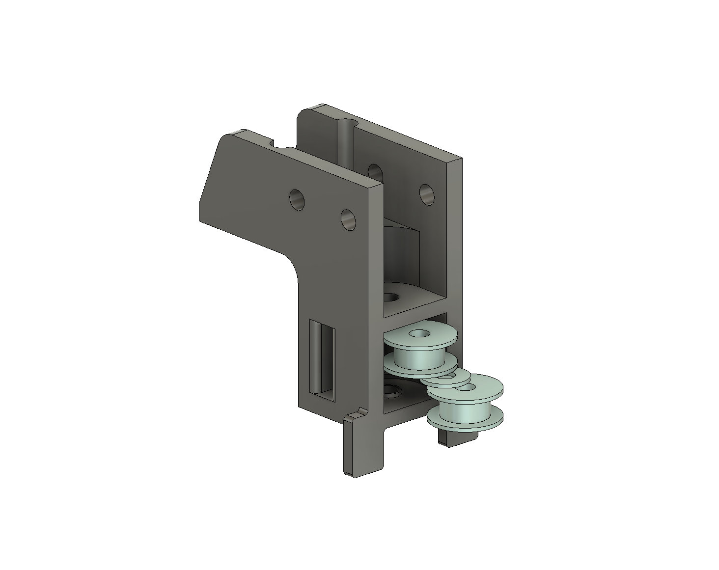
Now the MGN12H rails can be attached to the Y extrusions. While they are pretty easy to mount, if you have never done so before the important part is to ensure the rails are centered on the extrusions. You can print a rail alignment tool to simplify the process. Once the rails are attached we can assemble the Y carriages. The left and right Y carriages are identical. Each carriage takes two gt2 pulleys with one washer as a spacer between them.
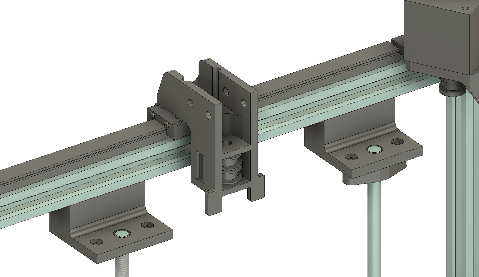
With the Y carriages attached we can now build the X axis and carriage. One of the strengths of this printer design is that you do not need a precisely cut X extrusion. As long as the extrusion is at least as wide as the frame inner dimensions it should work and longer extrusions are ok to use. The X linear rail needs to be shorter than the frame inner width minus 50mm in order to fit between the Y carriages. Realistically it can be ~100mm shorter than the frame inner dimension without losing any travel distance due to the width of the X carriage.
Start by attaching the MGN12H rail to the X extrusion such that the rail is centered on the extrusion. Then slide the extrusion into the Y carriages with the rail oriented down toward the printer bed. You can now attach the X carriage of your choice to the MGN12H carriage. I'll use the single bowden setup for this example.
You're now ready to feed the GT2 cables. Start with the front right bottom cable. Feed the end of the GT2 cable through the rear of the carriage and secure it in the track using a cable clamp. We will use the other end of the cable to set tension so you don't need much tail on the front side. Feed that cable through the bottom GT2 pulley on the right Y carriage. If lined up correctly it will come out the front hole of the Y carriage. Then pull the cable through the bottom hole of the pully block. Once again, if aligned correctly the cable will pop out the left size of the block. Follow it over to the bottom right side of the left pulley block - it will come out the bottom back of the pulley block. Pull it to the rear left motor and wrap around the timing pulley. Then back up to the bottom pulley on the Y carriage and then through the bottom left front hole in the X carriage.
Now you need to set the tension of the cable. Attach the cable clamp but keep it loose. With one hand pull on the tail of the GT2 cable - about as strong as you'd pull a few rubber bands to stretch a few inches or as hard as you'd pull to stretch a balloon before inflating it. It's not a LOT of tension and over tensioning could cause binding and alignment issues. While you have the cable under tension tighten down the cable clamp.
You can repeat the process for the other cable. Start with feeding through the back of the X carriage and follow the holes and channels around the printer like you did for the previous cable. If you've done it right when you manually move the cable the carriage moves in a diagonal direction. Make sure to check the cable and ensure that it's seated properly in all of the pulleys
Finally you will need to install the Y endstop holder. Endstops come in a few different varieties with different mounting holes so the printer system includes a couple variations of endstop holders to account for three of the most common patterns. The easiest mount to use with the most common long endstop is the 'Endstop Holder Large' on the outside of the front-left of the frame:
You can adjust the position of the endstop holder once you have the endstop installed. It's a bit of personal preference on whether the endstop should trigger when the nozzle is aligned with the front of the build - eliminating printing offsets and simplifying constraints - or whether the stop should trigger at the furthest extent of the axis - where the extra room can be used for purging or parking. Either option will suffice.
Congrats, your X/Y gantry is installed